

Welcome back to our exciting series on stage lighting design! In previous parts, we covered the basics, introducing the concept of lighting and its objectives. We also discussed the controllable properties of light, the importance of lighting angles, and color. Now, let's move on to lighting systems and their role in stage lighting design.
Lighting Systems
 Now that we understand the objectives of lighting design and have a good grasp on the properties that we can control to help achieve this, let’s look at the various components that make up a lighting system.
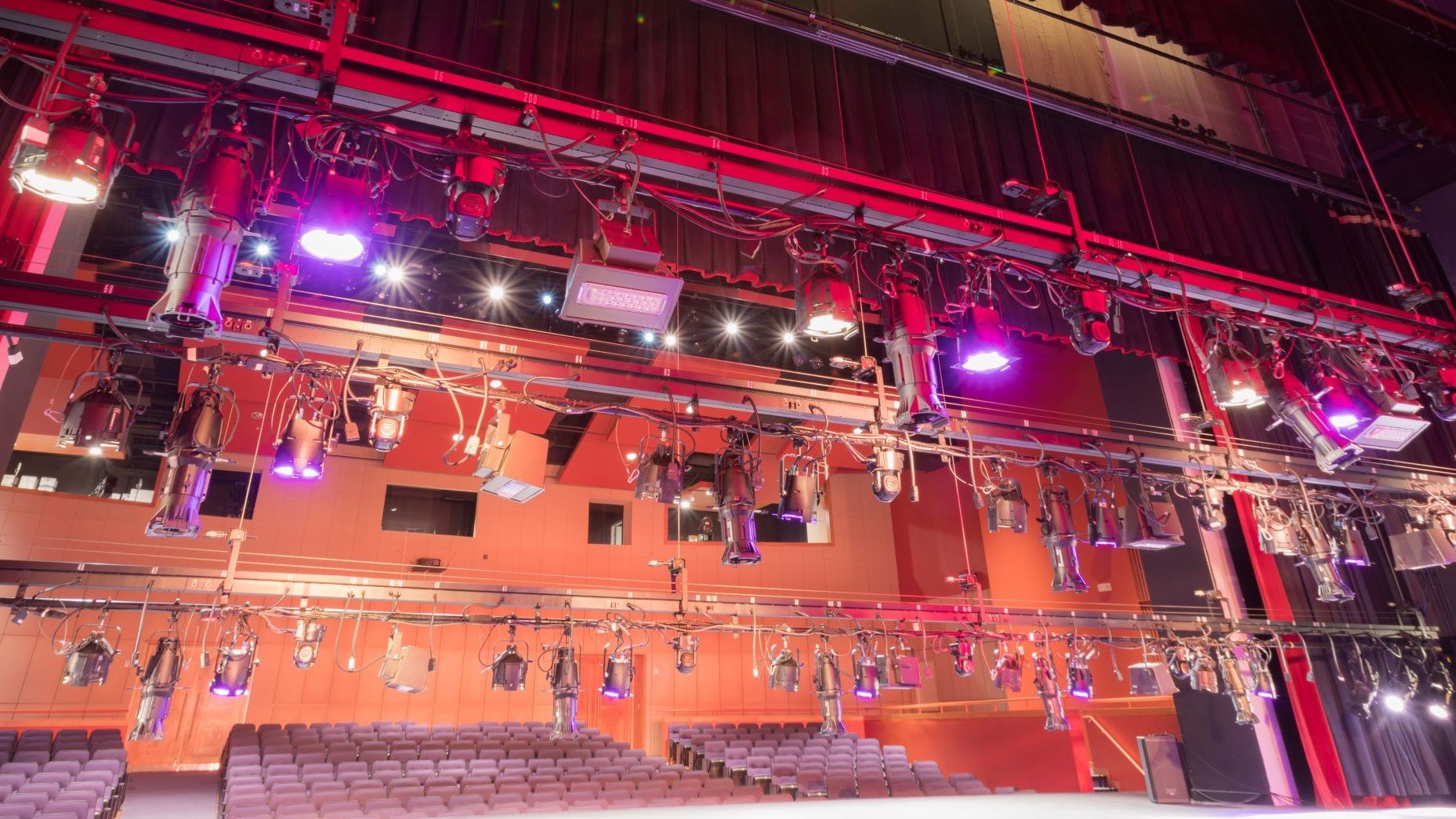
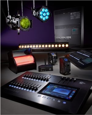
A lighting system will generally consist of a number of fixtures (rigged in different places in the theatre space), dimmers and power distribution, a cable infrastructure, and a lighting control desk.
Your theatre might have a combination of tungsten stage lights and LED fixtures. In order to control the intensity of the tungsten lamps, they will need to be plugged in to a dimmer, which is in turn connected to the lighting desk. Let’s take a look at each individual component in the system.
The lighting console
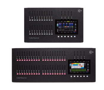 Sometimes simply referred to as the lighting desk, or lighting board, this is a key component of the lighting system. Most modern consoles have a digital interface that you use to program the lighting, but some will still have some faders for manual control of the lights.
Each console will behave slightly differently, but all should have the same basic functionality. You will be able to select the lights you want to use, set their intensity, change their color (if they have the ability) and record the state you have created. Each new lighting state is called a “cue.” When you are recording each cue, you will also need to set the cross-fade time – the time it will take for the change to happen from one cue to the next.
On most consoles, each light is called a “channel” and each channel will have its own unique number that you use to select and control it with. Irrespective of whether you are using faders or a keypad to select the lights, the channel number needs to be assigned first. To assign channel numbers, you need to patch the lights into the console. Patching is the process where you tell the lighting desk which kind of lights are hanging in your rig and which channel numbers you want to use to control them. Each console will have its own unique way of patching, so take some time to read the manual before you get started. We assign channel numbers to the lights as it gives us an easy way to talk to (and about) the rig.
Instead of saying “please can you turn on the third light from the left on the second lighting bar”, we can simply say “please turn on Channel 5.” the advantage of this system is that you get to choose the numbers you want to use – so think about a numbering system that will make sense to you.
Once all your cues have been created, you will be able to play them back in sequence for your show.
 Dimmers
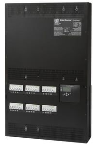
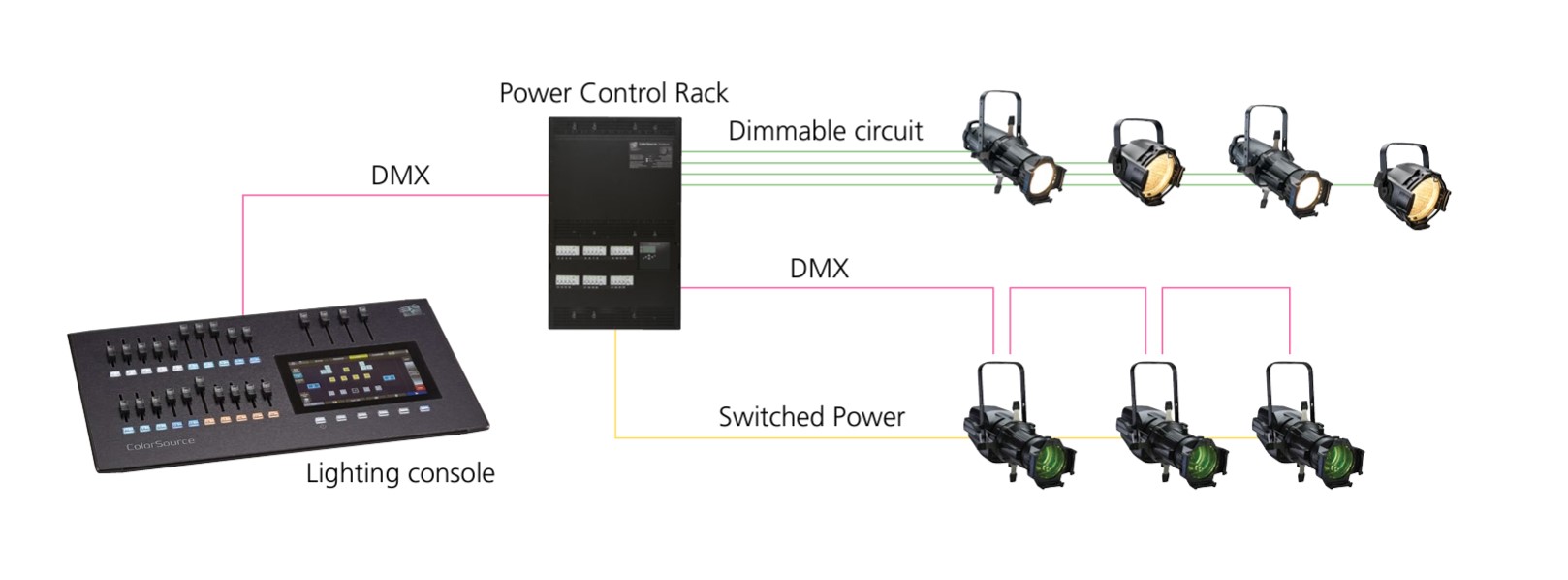
If you are using tungsten luminaires, you will need to connect the light to a dimmer in order to control the intensity. A dimmer is an electronic device that is used to vary the intensity of a lamp. Dimmers are typically located in a separate room in the theatre and each line of dimming is then wired back to the various lighting positions in the theatre. When you are patching your lights into the console, you are actually patching the dimmers – the light being connected to the dimmers. When you bring up a channel on the lighting desk, you are controlling the dimmer and the dimmer is controlling the intensity of the light. Dimmers work by varying the voltage that is supplied to the lamp. The lower the voltage, the dimmer the light.
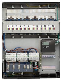 Switched Power
If you are using LEDs (or moving lights if you have them), they will not be connected to a dimmer. LEDs and moving lights should NEVER be connected to a dimmer as this will likely cause damage to the fixture. LEDs will need to be plugged into a mains voltage or ‘live power’ supply. Depending on the types of lights you are using, and the electrical installation at your theatre, you might encounter different power connectors. If you have LEDs and tungsten lights in your theatre, you will most likely have two different types of lighting sockets that you can plug lights into. We tend to use different power connectors for lights that need to be dimmed and ones that need mains power to prevent any accidental damage.
Some power control systems can be either a dimmer or a mains power circuit on a per-channel basis. It is worth making sure you know and understand the type of system that is installed in your theatre.
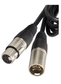 Data
Data
Once we have rigged the lights and plugged them into their outlets, we need to also make sure that there is a link between the lighting desk, dimmers, LEDs, and moving lights. We use a dedicated digital data called DMX (or DMX-512A as it is known officially) as the interface between the lighting console and lights. A DMX (or “data”) cable is used to link the lighting desk to the dimmers (to control intensity) and the LEDs.
In most instances, the DMX connector is a 5-pin XLR connector although some manufacturers will use a 3-pin connector instead.
As the console is the source of the DMX data, the data connection needs to start here. From the console, we usually link to the dimmers first, before linking to the LEDs and moving lights. Most theatre installations will have these links already in place, but it is good to know that they exist in case something goes wrong and you need to do some troubleshooting. If you are adding new lights into the theatre, then you may need to link them to the data network as well as give them power. In more complex systems, you may have more than one line of DMX. If your console has more than one DMX output, it means that you are capable of controlling bigger lighting systems. Each DMX output is called a “universe” and each universe can control 512 addresses.
In lighting systems where you are using dimmers to control the intensity of the lights, usually the number of the socket you plugged the light into will correspond to the channel number you will use to control it. You can also use the ‘patch’ function to change these number allocations.
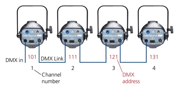
When you are using LEDs (or moving lights) you also need to give each fixture a unique address. This digital address is the lighting desk’s way of knowing how to control the particular LED fixture you have connected. With a dimmer, there is only one control parameter – intensity. With an LED fixture, there is more than one control parameter. You can control the intensity, but you can also control color and may have a strobe parameter. When you assign the addresses to the lights, you should be sure to leave a big enough gap between addresses so that none of the control parameters overlap each other as this can cause some problems further down the line.
Most modern consoles are capable of assigning addresses to the fixtures for you, using a feature called RDM (Remote Device Management) – so it is one less thing for you to think about!
Once your fixtures have been rigged and patched, you can ‘flash’ all the channels to make sure that everything is working. You are now ready to start focusing the lights.
What is “patching”?
Patching is how we connect the lights in our rig to the lighting console. We have already plugged them into the dimmer or power outlets, and where needed, connected the DMX. Patching is the virtual connection between the instruments and the console. As the size and complexity of the lighting rig increases, there is more and more information that the lighting desk needs to distribute to the units on the rig. Patching is a way of ensuring that you can control the right lights in the right way and ensure that only information intended for a specific instrument is actually delivered to that instrument. It is a way of organizing the lights and channel numbers into a logical system that will be easy to work with and recall. There are two types of patching systems, or methods, that you are likely to come across: Hard- and Soft-patching.
Hard patching is the system in which the luminaires are connected directly to the dimmer outlet (or switched outlet) on the lighting bar.
Soft patching occurs at console level and is a way of telling the console which lights you have rigged and which channel numbers you want to use to control them with.
Patching gives us a way to talk to (via the lighting desk) and talk about (to our colleagues) the lighting rig. If, every time we wanted to use a light we had to say (or type in) “third light from the left on the fourth electrix” it would take ages to get any work done. So, we allocate a dedicated number to each light on the rig which we call a “channel number” or simply a “channel.”
The advantage of doing this is that we get to decide on a numbering system that makes sense to us. You might decide that you want your FOH lighting to be Channels 1 thru 8 and the wash lights to be Channels 101 thru 108 – for no reason other than it makes sense to you!
Patching allows you to do this. A channel number can be either single fixture like a Source Four, or it can be a fixture like an LED or a moving light, or it can even be a number of individual lights that you may want to control together, like your houselights, for instance.
When you are patching conventional (tungsten-based) instruments, one dimmer is typically patched to one channel number. There are some exceptions to this, but that is the general rule, as you probably want to be able to control each light individually.
When patching conventionals, the type of light is not important – all you are patching is the dimmer. When patching, we talk of the dimmers as “addresses”. Each dimmer is an “address”. Dimmer 1 = Address 1, and so on. When it comes to controlling LEDs (or moving lights), there is more than one control parameter. With a tungsten source, you are only controlling intensity. With a moving light, you can also control color, position, gobo, and any number of other parameters. Each parameter requires its own address so that the console knows which parameters to send instructions to. All you need to do is determine the STARTING ADDRESS and the fixture and console will work out the rest.
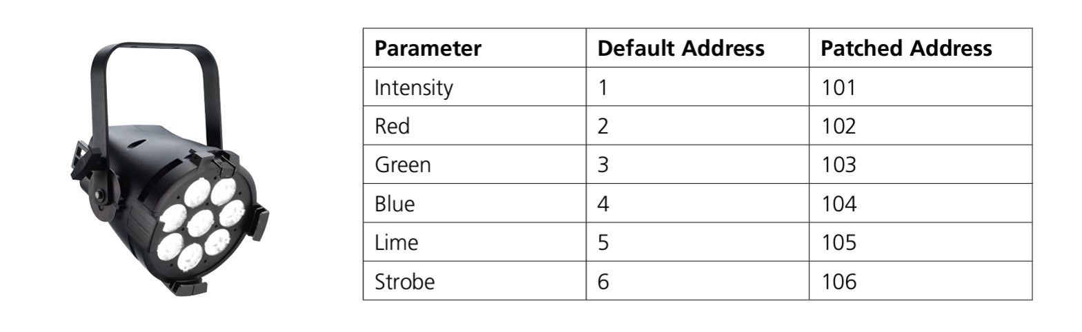
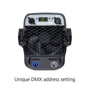 When you are setting the addresses of the fixtures, each light must have its own unique address and they should not overlap. There will be a way to set the address of the fixture on the light itself – the user manual for your lights will guide you through this process.
If you found this information helpful, don't miss our blog series dedicated to the art of stage lighting design, right here:
Stage Lighting Design, Part 1: Introduction to Lighting
Stage Lighting Design, Part 2: Objectives of Lighting Design
Stage Lighting Design, Part 3: Controllable Properties of Light
Stage Lighting Design, Part 4: Types of Lights
Stage Lighting Design, Part 5: Lighting Angles
Stage Lighting Design, Part 6: Color
Stage Lighting Design, Part 7: Lighting Systems
Stage Lighting Design, Part 8: Planning Your Design
Stage Lighting Design, Part 9: Getting Technical
Stage Lighting Design: Glossary
This blog series is an adaptation of our free digital guide, Stage Lighting Design: An Introduction, based on content written by ETC Outreach and Training Specialist, Declan Randall.
To gain a deeper understanding of stage lighting design, take a look at our free digital guide, Stage Lighting Design: An Introduction, and accompanying posters. For further information on the wide range of lighting products manufactured by ETC, visit etcconnect.com.